Line Following Robot Competition (LFR)
ENMT221 Mechatronics Design Project · Team of 4 · ATmega328 / KiCad
Summary
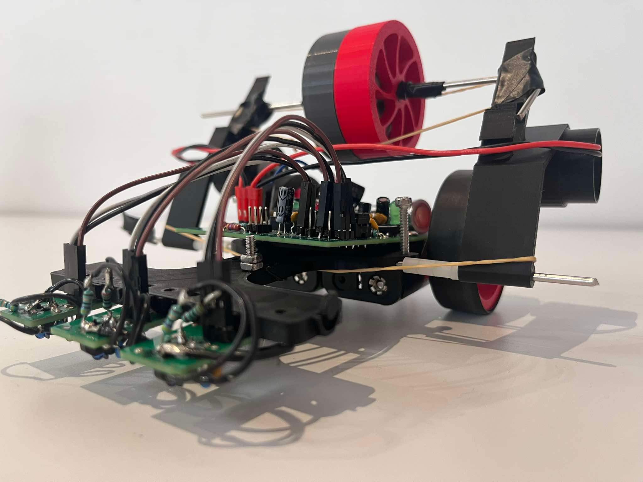
Designed and built a fully autonomous line-following robot that completed a black-line course in 14.939 seconds, placing 8th out of 36 teams. The project involved full-stack mechatronics integration: custom PCB design in KiCad, embedded C++ firmware on an ATmega328, MOSFET motor driver implementation, optical sensor debugging, and iterative mechanical prototyping. Despite early PCB and sensor design faults, the final system achieved reliable, repeatable high-speed performance under competition conditions.
System Overview
Built around an ATmega328 microcontroller with a custom-designed main PCB and 5 modular sensor PCBs, a MOSFET motor driver stage with flyback protection, 4×AA battery supply with onboard 3.3 V regulation, and TCRT5000 reflective optical sensors. The PCB was designed in KiCad, exported as Gerbers, manufactured externally (JLCPCB), then assembled and debugged in-house.
Electrical & PCB Engineering
Motor control: Low-side N-channel MOSFET switching with direct battery drive, flyback diodes for back-EMF protection, and a decoupling network for supply stability.
Power system: 4×AA pack (~5.5 V nominal) regulated to 3.3 V via a linear regulator, with strategic decoupling placement and test points for debugging.
PCB design: Multi-board architecture (main + sensor modules) with trace-width separation for power vs signal, short signal routing to reduce noise, and a crystal oscillator for clock stability. Post-manufacture issues — incorrect capacitor polarity footprints, sensor PCB miswiring, and a button pin mapping error — were diagnosed via multimeter testing and corrected through trace cutting and jumper rewiring, restoring full system functionality.
Sensor System & Debugging
Initial sensor boards failed to detect line transitions due to incorrect phototransistor routing. Fixes included correcting emitter-to-ground routing, adding pull-up resistors, reconfiguring phototransistor biasing, and rewiring traces via jumper fixes. The final configuration used 3 sensors (left, centre, right) for closed-loop control.
Control Strategy
A reactive control algorithm was implemented in embedded C++: threshold-based line detection with left/right motor speed modulation and a centre sensor for forward stabilisation. Originally intended PID control was abandoned due to early sensor hardware instability. Adding the centre sensor improved average lap time by ~4.9 seconds by reducing oscillation. Mechanical grip optimisation (added mass and shaft roughening) further reduced average times to 18.6 s, with a best run of 14.939 s.
Mechanical Design
Fully 3D printed PLA chassis with iterative wheel diameter testing (50–70 mm). Final 55 mm wheel chosen for torque–inertia balance, with a lowered centre of mass for stability and adjustable sensor mounting height. Mass distribution was tuned to increase motor traction without exceeding competition limits.
Performance
Best recorded time: 14.939 seconds — 8th place out of 36 teams. Achieved stable, repeatable runs under competition time pressure.
My Contribution
Main PCB schematic and layout refinement in KiCad, motor driver and power routing design, sensor debugging and trace correction, embedded firmware (Arduino C++), control algorithm implementation, and hardware bring-up and fault isolation.
Links & Artifacts
GitHub repository — firmware and documentation.
Key Skills & Tools
PCB & Electrical
- KiCad schematic capture and PCB layout
- Gerber export and external manufacture (JLCPCB)
- MOSFET motor driver design with flyback protection
- Power regulation and decoupling strategy
- Hardware debugging, trace cutting, and rework
Firmware & Control
- Embedded C++ (Arduino / ATmega328)
- Reactive closed-loop control algorithm
- TCRT5000 optical sensor interfacing
- Threshold-based line detection with motor modulation
- Hardware bring-up and fault isolation
Mechanical & Systems
- 3D printed PLA chassis design and iteration
- Wheel diameter optimisation (torque–inertia trade-off)
- Mass distribution tuning for traction
- Full-stack mechatronics integration (team of 4)