STM32 Step Counter – Real-Time Embedded Wearable System
STM32C071 (Arm Cortex-M0+) · Bare-metal C · SPI / I²C / DMA / PWM
Summary
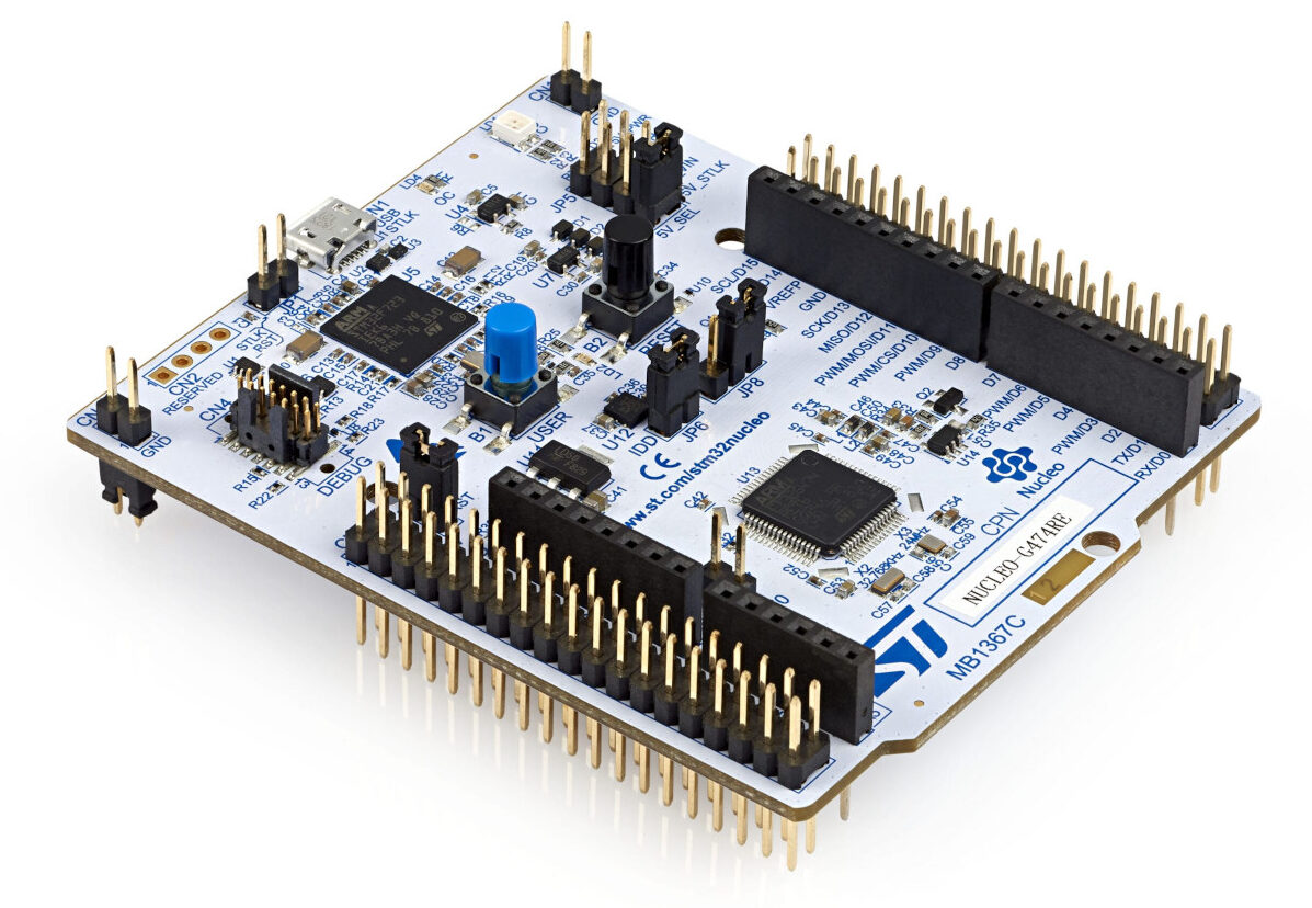
Designed and implemented a real-time step counting system on an STM32C071 (Arm Cortex-M0+) microcontroller in C. The system reads motion data from an LSM6DS accelerometer over SPI, filters the signal, detects steps using a peak–valley finite state machine, and provides real-time user feedback via an OLED display, RGB LEDs, and a PWM-driven buzzer.
The firmware runs on a bare-metal cooperative scheduler (no RTOS) and uses DMA for both ADC and I²C transfers to maintain responsiveness. Step detection operates at 50 Hz and was tuned using live serial plotting. The final system reliably counts pedestrian steps, tracks distance, and provides a hardware-level goal alert.
System Overview
The device tracks step count, estimated distance (1 m per step), and progress toward a user-defined daily goal (500–15,000 steps, set via potentiometer and snapped to 500-step increments). User feedback is provided through three OLED screens (Steps, Distance, Goal Progress), progressive RGB LEDs at 25/50/75/100% of goal, and a 5-second PWM buzzer alert on goal completion.
Core hardware: STM32C071RBT6 at 12 MHz HSI, LSM6DS IMU via SPI2 (6 Mbit/s, 16-bit transfers), SSD1306 OLED via I²C1 + DMA, ADC1 + DMA for joystick and potentiometer, TIM16 PWM for buzzer (~250 Hz), TIM2 PWM for variable LED brightness. All peripheral configuration was generated in CubeMX and refined manually.
Step Detection Algorithm
Signal conditioning: All three axes (X, Y, Z) are read at 50 Hz. A 20-sample circular-buffer moving average is applied per axis (window sizes of 1, 3, and 30 were tested; 20 gave the best noise–responsiveness balance). Magnitude-squared is computed as mag² = x² + y² + z², scaled by 1,000,000 before threshold comparison.
Detection logic: A two-state FSM (WAITING_FOR_PEAK → WAITING_FOR_VALLEY) uses an upper threshold of 300 and lower threshold of 260. Crossing above 300 arms the system; crossing below 260 increments the step count. The 40-unit hysteresis gap prevents double-counting within a single stride. The FSM itself acts as the debounce — no explicit refractory timer is needed. Thresholds were tuned empirically using live serial plotting in VS Code.
Real-Time Architecture
A cooperative scheduler runs inside a superloop using HAL_GetTick() (1 kHz SysTick timebase). Task frequencies: 50 Hz for button + IMU read + filter + step detection; 4 Hz for display, LED, and joystick updates; 2 Hz for status blink. DMA is used for ADC multi-channel scanning (pot + joystick X/Y) and I²C OLED transmission, preventing blocking during screen refresh and analog sampling.
The project follows a layered module structure: drivers/ for register-level peripheral drivers, middleware/ for filtering and step detection, tasks/ for application behaviours, and app/ for orchestration. Hardware abstraction is isolated from application logic. The system runs within a 512-byte heap and 1 KB stack on on-chip SRAM only.
Calibration & Validation
Signal tuning was performed using USART2 debug output with real-time accelerometer X/Y/Z streams, filtered magnitude output, and threshold overlays. Validation features built into firmware include a double-tap test mode (≤700 ms window), joystick-controlled artificial step increments, a manual +80 step debug button, and goal-alert verification via rapid step injection.
Artifacts
Key Skills & Tools
Embedded Systems
- STM32C071 (Cortex-M0+) bare-metal C
- SPI IMU integration (LSM6DS)
- I²C OLED with DMA (SSD1306)
- ADC multi-channel scan with DMA
- PWM generation (TIM2, TIM16)
- CubeMX peripheral configuration
Signal Processing
- Moving-average filtering (circular buffer)
- 3D magnitude-based motion detection
- Peak–valley FSM step detection
- Hysteresis tuning and empirical calibration
- Live serial plotting for validation
Firmware Architecture
- Cooperative scheduler (no RTOS)
- Non-blocking superloop design
- Modular C project structure
- Hardware abstraction layers
- Real-time UART debugging